Asynchronous FIFO Clock Recovery
- Homepage
- Services
- FPGA Cores
- Asynchronous FIFO Clock Recovery
- FPGA Cores
- Services
Traditional digital audio interfaces such as SPDIF, AES/EBU, HDMI and other rely on audio clock recovery from the data stream on the receiver side. This is usually done using an analogue PLL (phase-locked-loop) circuit. Quite often directly in the digital audio receiver chip itself. Unfortunately, the recovered clock is far from being perfect. Due to high PLL bandwidth the recovered clock suffers from high phase noise levels (jitter) of various origins. Bit patterns, mains loops, electromagnetic interference, impedance mismatch on the transmission line, to name a few. To put it into layman’s terms, this is one of the main reasons why different digital audio transports, cables, connectors, etc. sound differently, although they shouldn’t. Bits are bits and they should be the same every time, right? Well, bits might be the same, but the clock - timing information is certainly not, as it can be adversely affected by many factors. There are a few ways to tackle the problem, or at least minimize the negative effects of the standard PLL. Sometimes a secondary PLL is used to clean up the clock a little bit. By far the most popular solution is using an asynchronous resampler, which in theory could work well, but in practice it suffers from very similar imperfections as PLLs. To make things worse, asynchronous resamplers basically transform and irreversibly embed the timing issues into the audio data, because they recalculate the audio data from momentarily determined incoming sampling rate, which keeps changing all the time, to a new stable clock domain. And all that with real word limitations, such as finite buffer sizes, resolution of the frequency estimator and limited number of resampling filters coefficient sets available.
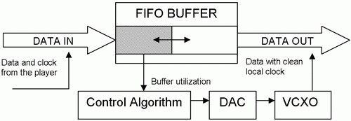
Our ethos is to mess with the audio data as little as possible. Therefore the only way is to come up with something clever for the clock recovery. Instead of the standard analogue loop, we use a technique that we call DBLL – Digital Buffer Locked Loop. Incoming audio data is stored in an asynchronous memory buffer and effectively stripped of the original jittery timing. The utilisation of the buffer memory controls the frequency of a local low-jitter voltage-controlled oscillator to ensure that the buffer memory is utilised in an optimal manner. The block diagram of the DBLL system is shown below.
This method allows seamless synchronization of both time domains. Here are some key features of the method.
Completely asynchronous
Low inherent delay
Instant playback – no locking time
Digital oscillator control
Adaptive loop algorithm
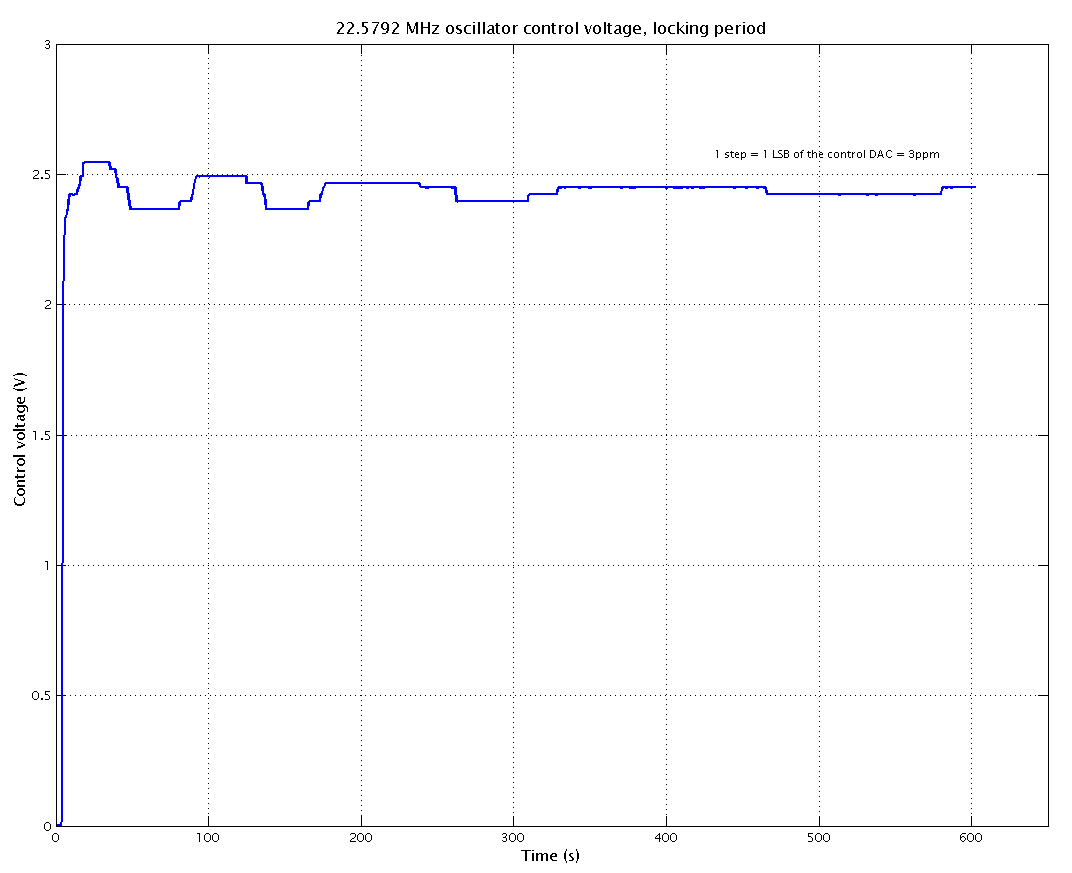
Our algorithm controlling the local oscillator adjusts the frequency in tiny steps with individual frequency corrections dozens of seconds apart, which makes the local adjustable oscillator look like a fixed frequency one. Thanks to adaptive nature of the algorithm this behaviour can be achieved with only a few tens of samples of the buffer memory depth. To achieve the best performance of the local audio clock we use custom made oscillators with extremely low phase noise. An alternative to the VCXOs is a DDS clock synthesizer, but such a thing is very expensive when done right. Cheap DDS chips, that some manufacturers happily use and claim ultimate performance, produce very rich non-harmonic content, negatively affecting the clock stability and the final result – the sound.